A New Method for Determining Paleocurrent Direction in Sandstones.
Introduction:
About twenty years ago I developed a technique for determining the paleocurrent direction in quartz rich sands with planer bedding but I did not develop it further because after finishing my masters degree (for which this project was my thesis topic) I became employed in the petroleum exploration industry as a geophysicist. Later I changed companies and also changed my field from geophysics to geology, working first in the exploration division and later in the engineering and field development division. Since I was not in the Research and Development arm of a major corporation during these years there was no corporate interest in developing the technique and I lacked the time to do it on my own. After the industry fell apart in the mid 80's I taught physics and physical science at a two year technical college and although they had a laser and electro-optics department they were only interested in training technicians not in developing new applications. For the past three years I have been teaching geology and physics at a large community college and so am back into academics. Consequently I have a little time a little room and some institutional moral support (though no direct financial support) for setting up a new lab for developing the technique further.
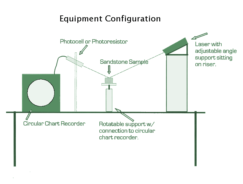
The purpose of this paper is to describe the technique and provide an illustration of my previous lab set up. This will give some background information for those wanting to set up their own lab and will give an outline for the studies I plan to begin this summer, the results of which I will post on this site.
Discussion of the technique:
Four lines of evidence and logic are needed to explain and justify this technique and further extensions of it. The first establishes the coincidence between the long axis and the optic axis of mono-crystalline quartz grains during weathering, abrasion, and sedimentation. The second describes the behavior of light reflected from a polished surface of translucent material-specifically uniaxial crystals such as quartz. The third establishes the behavior of elongate grains being deposited from the water flowing in a laminar flow regime, and the fourth establishes the coincidence of the average grain orientation and the direction of the greatest permeability.
I. The statistically coincident relationship between the optic axis of a quartz sand grain and its longest dimension was established by Griggs (1936, "Deformation of Rocks Under High Confining Pressure, "Journal of Geology, 44:541-577) and Griggs & Bell (1964, "Experiments Bearing on the Orientation of Quartz in Deformed Rocks," GSA Bull. 49:1723-1746). Wayland (1939, "Optical Orientation in Elongate Quartz," American J. Sci. 237:99-109) showed that for the highly abraded and well rounded St. Peter sandstone samples he examined there was a statistically coincident relationship between the optic axis and the long axis of the sand grains. My work verified this relationship for the samples I examined. Consequently, if the average orientation of the optic axes of the quartz grains in a sandstone is determined, (assuming the grains are elongate, are oriented, and are mono-crystalline, assumptions that are valid for the majority of sandstones deposited in fluvial or marine environments), then the orientation of the long axes of the grains is also determined.
II. The alignment between the average individual long axis orientation and the flow direction of the depositing fluid has been shown, verified, assumed, and/or explained by many authors over the decades. The original work was by Wayland (1939); Martini (1971, "A Test of Quartz Grain Orientation as a Paleocurrent and Paleo-environment Indicator," J. Sed. Pet. 41:60-68). Martini, as did the others before him, concluded that sand grains do indeed line up with the current direction when they are deposited.
III. Brewster's angle is the angle at which a vertically polarized beam of light is refracted into a translucent material rather than being reflected from it. It is the angle of incidence at which the angle of reflection and the angle of refraction are separated by 90o (see
IV. If a horizontally polished surface on a sandstone composed of predominately quartz grains whose optic axes are approximately horizontal is illuminated with a beam of light from a vertically polarized red laser and the angle of incidence is about 57.3o, then the intensity of the reflected light (which will no longer be a tightly collimated beam due to scattering from the edges of the sand grains etc.) will be a minimum when the direction of the average optic axis alignment is parallel to the incident beam and the reflected line cone. The intensity of the reflected light will not be zero for at least three reasons:
Diagram of a previous lab setup for doing this type analysis.
